Developments in Agricultural Drainage in Illinois
content
 |
Richard CookeAssociate Professor of Agricultural EngineeringPhone: (217) 333-0944 E-mail: r-cooke@illinois.edu |
||
Subsurface drainage (tile) systems are ubiquitous in Illinois. According to USDA estimates, some 10 million acres, about 35 percent of the total agricultural area in the state, are tiled. These drainage systems have a significant effect on production agriculture and water quality of the watersheds in which they occur. Without tile drainage, crops could not be economically grown on much of what is now the most productive land in the state. Drainage not only removes excess water, leading to a reduction of crop stress and increased yield, but it also allows earlier access to the field for planting, harvesting, and other agrotechnical operations. For hundred of years, the objectives of drainage have been to reduce excess water stress and improve the timeliness of field operations. However, for the past 40 years, added attention has been placed on reducing off-site transport of chemicals in tile water.
Some chemicals used in agricultural production, particularly nitrates, are very soluable in water, and thus are transported from agricultral fields in tile water. A 1999 report to Congress listed tile drainage as one of the main sources of high nitrate loads in the Mississippi River as it enters the Gulf of Mexico. High nitrate loads have been identified as a cause of hypoxia in the Gulf. In hypoxic zones, oxygen levels are not sufficient to support normal marine life. Nitrates have also been implicated in a number of health-related issues, including methaglobanemia, non-Hodgkins lymphoma and stomach cancer.
Much of the drainage research being conducted at the University of Illinois is related to both crop production and water quality issues. Research is being conducted on drainage water management, tile system layout, and subsurface bio-reactors. These best management practices (BMPs) have the potential to improve the quality of water that flows out of agricultural fields.
Drainage Water Management
In drainage water management, a control structure is placed at the outlet of a tile system to control the level of the water table in the soil (Figure 1). This method can be used to raise the water level after harvest, thereby reducing the nitrate concentration in tile effluent, or to retain water in the soil during dry years. Researchers are seeking to develop parameters for the operation of these systems in Illinois, where there are specific challenges associated with the implementation of this management practice. The major challenge derives from the fact that existing drainage systems were not originally designed for water table management, and that many of the drainage systems in the state are irregular—that is, the drains are not laid out according to a pattern, nor are they equally spaced. Several systems, both regular and irregular, have been retrofitted with control structures and monitored.
The results from these studies are preliminary, but they tend to support the conclusion that drainage water management can result in significant reductions in nitrate loadings from agricultural fields, and in all probability, to increased phosphorus loadings from surface runoff. However, these studies are also providing valuable insight into the nature of phosphorus transport in tile drains. Figure 2 shows the relationship between cumulative phosphorus load and cumulative flow in a retrofitted drainage system. Most of the phosphorus is transported in a few discrete events, and may result from preferential flow though cracks and root channels. After a control structure was installed on the tile, there was a reduction in phosphorus loading. It appears, therefore, that drainage water management has the potential to reduce phosphorus loads in tile effluent.
Subsurface Bio-reactors
The installation of subsurface bio-reactors is an attempt to provide a subsurface solution to a subsurface problem. In flat, tile-drained watersheds, such as are common in central Illinois, vegetative filter strips are not very effective, since much of the water that enters streams and rivers flows through subsurface tile drains, never coming into contact with the filters on the soil surface. Tiles are normally placed 4 to 5 feet below the soil surface. Because of the flatness of the land, there are few areas where wetlands can intersect these tiles. Subsurface bio-reactors do not suffer from these limitations, and unlike other edge-of-field treatment methods, they do not require that land be taken out of production.
Bio-reactors consist of wood chip and gravel media, placed underground, through which tile water is allowed to flow. These systems provide an alternate pathway and are designed so that there is no decrease in drainage effectiveness (Figure 3). The outlet of the bio-reactor is placed lower than the level of the existing tile, so water will more likely follow this pathway. However, should the flow capacity of the bio-reactor be exceeded, the water will pass through the existing tile outlet.
Figure 4 shows the relationship between inflow and outflow nitrate concentration for a bio-reactor in central Illinois. In this case, all of the nitrate is removed from the water that passes through the bio-reactor. However, only about 20 to 30 percent of the total flow passes through the bioreactor in a typical system. Research is being undertaken to increase this percentage, thereby increasing the efficacy of these systems.
Depth/Spacing Studies
While different combinations of depth and spacing may result in the same intensity of drainage, they differ in their effect on water quality. With this in mind, experiments have been set up to determine the design configuration that optimizes production benefits while having the least deleterious impact on the environment. Typically, these experiments consist of two or more drainage systems installed in sections of a field with fairly uniform soil type and topograpy. One section of the field serves as a control and is either undrained or has a conventional drainage system. On the other system or systems, the depth is altered, the spacing is altered, or both are altered. The cropping practice is identical over the entire field, thereby limiting (as much as is possible) any differences between the systems to the difference in drainage status.
The results from one such experiment are shown in Figure 5. At this site, two monitored subsurface tile lines were installed 2 feet below the surface. Two others were installed 3 feet below the surface, and a fifth monitored tile was installed 4 feet below the surface. With the exception of the deepest tile, each of these monitored lines was bordered on either side by a buffer tile placed at the same depth. Because of space constraints, the deepest monitored tile had only one buffer tile at the same depth. The buffer tiles were spaced 50 feet on either side of the 2-feet deep monitored tiles and 100 feet on either side of the other monitored tiles. The tile lines at 2 feet contributed significantly less nitrate-N mass loads than the tiles at 3 feet or the tile line at 4 feet. The average reduction for the 3-feet tile lines, when compared to the tile line at 4 feet, was 22 percent. The average mass load from the 2-feet (0.61m) tiles was 51 percent less than that for the tile line at 4 feet. Similar research is being conducted on 12 representative soils in the state. The data from these experiments will be used to make recommendations about the design of new drainage systems.
Updating the Illinois Drainage Guide
Typically, information on the depth and spacing of tile drains in Illinois is obtained from the Illinois Drainage Guide. For a specified soil, the guide gives a combination of depth and spacing that will optimize yield, improve trafficability, or both.
Currently, drains in Illinois are typically installed at a depth of 4 to 5 feet at spacings of 70 to 150 feet. Originally, these tile systems were designed for the sole purpose of quickly removing excess water from the plant root zone to prevent wet stress and to improve crop yields. These recommendations were made before there was widespread concern about water quality. The revised guide will reflect new developments in drainage since the last edition. Most of these are related to new equipment and materials, widespread use of computers, and water quality considerations. It will include information not in the current edition, including information on pipeline crossings, water and sediment control basins, drain fields for septic systems, design of drainage water management systems, and design charts for smooth-walled pipes.
The revised Illinois Drainage Guide will include a compact disc in addition to the paper document. The disc will include all of the depth and spacing information, but in easy-to-use interactive tables. Based on soil type and location information supplied to the program, the user will be presented with curves showing relative yield and nitrate loads as functions of depth and spacing. There will also be an internal economic calculator that can be used to determine the rate of return associated with each depth-spacing combination, if drainage costs and grain costs are supplied. The user will be able to simulate various scenarios, such as the effect of drainage water management.
The new Illinois Drainage Guide will be updated continually as new research is conducted. Updates will be available online.
Tables & Figures
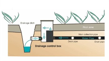 |
Figure 1. Drainage water management
control structure. |
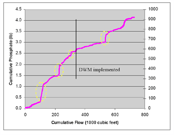 |
Figure 2. Effect of DWM on phosphate
loads from a tiled field. |
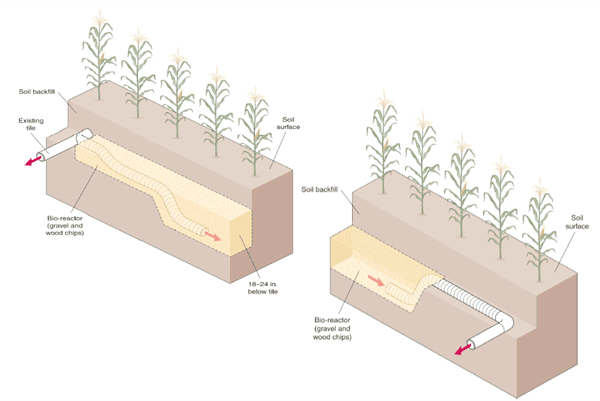 |
Figure 3. Schematic of edge-of-field
subsurface bio-reactor. |
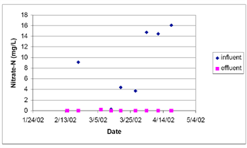 |
Figure 4. Relationship between
inflow and outflow nitrate concentrations in a subsurface bio-reactor. |
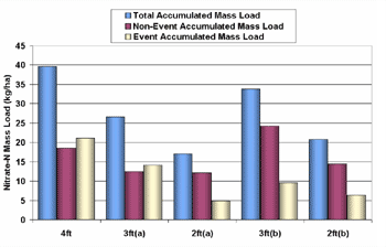 |
Figure 5. Effect of tile depth
on nitrate loading from a tiled field. |